
How to perform the Gaze Stabilization Test (GST)
If you have purchased the VORTEQ™ Assessment or Functional Assessment bundle, you will be able to perform the Gaze Stabilization Test (GST). GST is an assessment of the vestibulo-ocular reflex (VOR) in response to functional head movements. It is often paired together with the Dynamic Visual Acuity (DVA) or Functional Vision Head Impulse test (fvHIT™) to provide a starting point for rehabilitation.
For this test, the patient will move their head at different speeds but the optotype will always stay the same size, which has been determined from their static acuity score.
Screen setup
Select the Optotype Stimuli display source and set the screen size and patient distance in the System Default Settings before beginning the first test. A suggested patient distance will be identified for your screen dimensions. If the distance is too much for your room setup, then choose a smaller display input.

Protocol setup
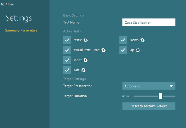
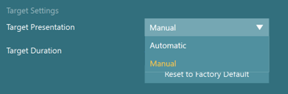
The default protocol is automatic, but you can also choose a manual target presentation. You can choose the options in Summary Parameters.
The default starting head speed is 70 degrees per second (Figure 4), but you can adjust that if needed.
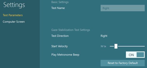
The metronome should be “ON” to give the patient feedback on how fast to move their head. The metronome sound will stop after each optotype appears to give the patient time to enter their response with the remote control. The sound will start again when they move their head.
Preparing for the test
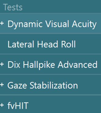
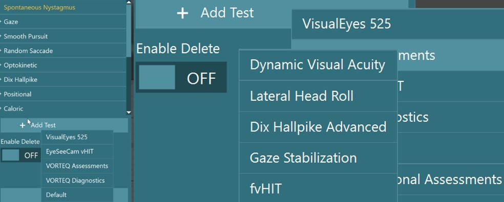
Select Gaze Stabilization from your default protocol if you have already set it up. If not, you can add it from the subtest menu for VORTEQ™ Assessment or Functional Assessment tests.
Make sure you have attached the sensor to the headband and turned it on.
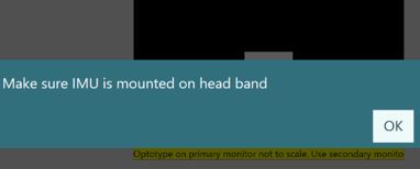
If the IMU is not turned on, you will see this error message.
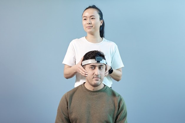
Once you have mounted the headband on the patient, you can hand them the remote control. Instruct the patient to press the arrow that matches the direction of the optotype they see during the testing.
As the clinician, you can also use the keyboard shortcut arrow keys or touch the software to select the direction of the optotype.
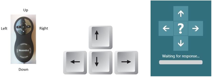
If the patient does not know the direction, they can tell you “I don’t know” and then you can click on the “?” on the screen to enter the “I don’t know” response for them.
There is also a five second timer (labeled “waiting for response”). If no optotype response is selected in 5 seconds, the “I don’t know” is automatically chosen. You can also use the keyboard spacebar to select the “I don’t know” response.

How to perform the Static Visual Acuity (SVA) test
If you have not already completed the Static Visual Acuity (SVA) test, then you must complete it before moving on. If you have already completed the SVA (in DVA or fvHIT™), then you can copy the values over and begin the GST with the first subtest.
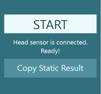
For the SVA test, the patient keeps their head still and responds to the direction of the optotype that appears in the white square on the TV screen.
How to perform the Visual Processing Time (VPT) test
Following the Static Acuity test, you will be prompted to complete the Visual Processing Time (VPT) test. This test presents the optotype two lines above the static acuity number and varies the time that the stimulus flashes on the screen.
As the patient gets correct responses, the stimulus flash time will get progressively shorter. The lowest VPT result is 30 ms. Any response over 70 ms is considered an invalid response and any following results should be interpreted with caution.
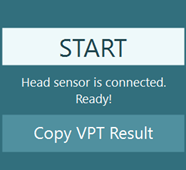
If you have already completed the VPT test in another test, then you can copy the values over and begin the GST with the first subtest.
For the VPT test, the patient keeps their head still and responds to the direction of the optotype that appears in the white square on the TV screen. The target display duration will change as the patient responds to the optotype. The goal of this subtest is to find the fastest duration time the patient can correctly identify the optotype.

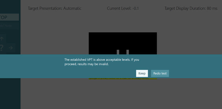
If the patient cannot identify the optotype correctly in less than 70 ms, you will see the following warning message.
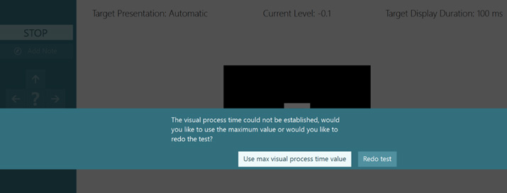
If the patient cannot identify the optotype correctly in less than 100 ms, you will see the following message warning you to either redo the test or use the max visual processing time value (100 ms). It is recommended that you proceed cautiously, as test results over 70 ms may not be valid.
If you perform multiple tests in the same session, you have the ability to choose which test you want to display.

How to perform the GST
Complete the four subtests in order.
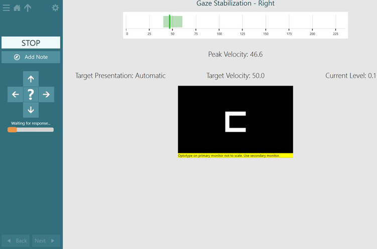
Have the patient move their head so that the speed of their head movement peaks in the green area of the velocity bar. Their head movement is the solid line. The acceptable range for head movement is the green shaded area.
When they peak the head movement in this area, the optotype will appear. You can see this on the screen as the direction arrows will become highlighted in white when the optotype has appeared.
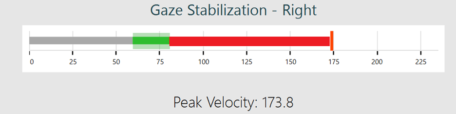
If the patient’s head movement is too slow, then you will see a red solid line that peaks before the green shaded area. You will see the progress of the head movement as a grey bar that ends at the red solid line. Instruct the patient to move their head faster and follow the beat of the metronome so they can reach the green shaded area.
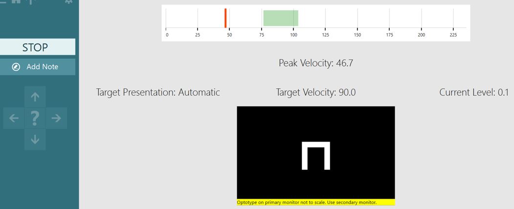
If the patient’s head movement is too quick, then you’ll see a red solid line that peaks after the green shaded area. You will see the progress of the head movement as a red shaded area that ends at the red solid line. Instruct the patient to slow down their head movements so they can reach the green shaded area.
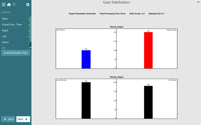
GST results
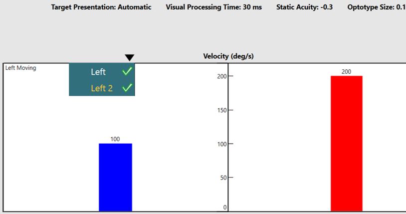
After you have completed the test, you will get a summary screen that reports the fastest head movement the patient could achieve, in each direction, while identifying the correct optotype direction.
If you have recorded more than one run in any direction, you can use the drop-down arrows to select which run you would like to display in the summary report.
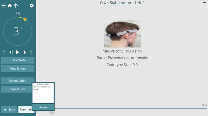
If you record with the room camera active, you can play back the video using the play arrow. You can also add notes to attach to your video playback timeline.
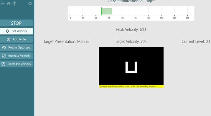
Manual test mode
You can also run the test in Manual mode. In this mode, you change the head velocity speed manually. When you are confident that your patient is accurately determining the optotype at a given speed, increase the speed until you reach the patient’s threshold and then set the velocity.
Troubleshooting
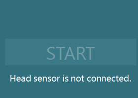
If the head sensor is connected via Bluetooth and the battery’s getting low, you will see this error message.
Presenter
